Manual for operation of the Asimow lab multianvil device
Version: October 15, 2003
This hyperlinked manual tree contains current step-by-step instructions for correct usage of the 1000-ton press, its heating and pressure control systems, the LabView interface, and the cubic and octahedral (castable or gasketed) modules. You may also want to look at Jed's multianvil page.
Errors, bugs, complaints, and suggestions for improvement of the manual or the experimental procedures are welcome, and should be brought to Jed or Paul.
- Basic operation of the press, including non-LabView pressure control
- The cubic module
- The octahedral module
- The heating system
- The LabView interface
- Checklists
- Troubleshooting
Basic operation of the press, including non-LabView pressure control
All the multianvil devices here run on the same press, a 1000-ton capacity press from Rockland Research Instruments. The principle of this device is quite simple. It has a large hydraulic cylinder able to exert a force of up to 1000 tons and a massive steel frame able to support that load and, through the rigidity of the frame, to "push back" and balance the forces so that the module is under compression but nothing is accelerating anywhere. The double-acting hydraulic cylinder has a main ram diameter of 13 inches (33.02 cm), or an area of 132.73 in2 (856.34 cm2). This cylinder has two internal reservoirs, an advance reservoir and a retract reservoir. The advance reservoir (the inlet near the bottom of the cylinder) acts on the full area of the ram and pushes the ram upwards; the retract reservoir (the inlet near the top of the cylinder) acts on about one-half this area and pushes the ram downwards. Critical principle: whichever reservoir we are pumping oil into, we need the other reservoir to be open to ambient pressure so it can drain rather than push back; we will see how to guarantee this below. Hence if we pump oil at a pressure of, say, 100 psi into the advance reservoir, the force pushing up on the ram is 100 psi x 132.73 in2 = 13273 lbs = 6.64 US Tons (this is about what it takes to overcome friction and make the ram move). If the retract reservoir is open to drain and there is empty space above the ram, it will move up under this force as we keep pumping in oil to maintain the pressure. This will continue until the top of the press frame starts to push back (through the multianvil module), at which point the system can achieve force balance and the ram stops moving. The pressure readout on the DP41 panel meter on the pressure control box is calibrated in US Tons of load when pumping the advance reservoir; the conversion to oil pressure is 1 Ton = 2000 lbs = 15.07 psi x 132.73 in2. So the limit of 1000 Tons corresponds to a maximum oil pressure in the advance reservoir of ~15000 psi ~ 1000 bars. To move the ram down (as at the end of an experiment), we decrease the pressure until the advance reservoir can be vented to the drain reservoir in the yellow enerpac pump and then pump oil into the retract reservoir. It takes an apparent pressure reading of about 13 Tons to move the ram down, but remember that the area that the retract resrervoir work on is smaller; the oil pressure is twice as high but the force to move the ram either way is the same.
The rail system for moving modules into the press
We have two multianvil modules, the cubic and octahedral devices. These are massive and difficult to carry around, so the press has a double-sided rail system to exchange these modules into the press. The cubic device is in front, the octahedral device is in back. Each module sits on a carriage (an aluminum plate with four rollers) that rolls on a pair of rails. There is a retaining pin to keep each carriage locked in either the fully withdrawn position (for storage and run assembly) or the fully inserted position (centered above the ram). Rule: Always keep the retaining pin fully inserted except when rolling the modules in or out. The carriages will only roll when the weight of the module is supported by the wheels on the rails, so at the end of a run you need to guarantee that the ram is withdrawn until the wheels take up the weight and a small gap opens between the carriage and the Aluminum plate fixed to the ram. Rule: Always verify that nothing is in the way of the wheels, either when rolling the module in or out, or when lowering it back onto the rails. This especially applies to thermocouple leads, which can get cut or shorted by wheels running over them.
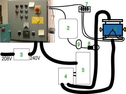
Overall schematic of pressure system
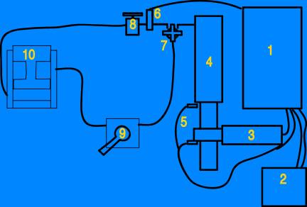
2. LabView control running on PC
3. Motor
4. High-pressure cylinder
5. Travel limit switches
6. Pressure tranducer
7. Four-handled valve to isolate immersion pump from advance reservoir
8. Two-stage pumping valve
10. Main ram
The enerpac immersion pump (yellow thing on the floor)
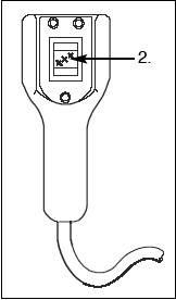
This pump is for rapid advance of the ram to make up the gap at the beginning of a run, before high-pressure loading can begin, and to retract the ram to lower the module onto the rails at the end of the run. The official Enerpac manual for this device is here; the model number is PEJ1401B. The pump is operated from the remote handle that hangs over the top of the press:
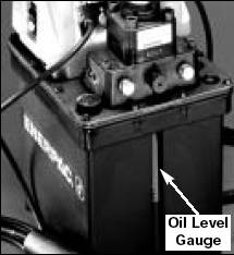
The oil level indicator on the front of the immersion pump should always show clear green oil at an acceptable fill level, no matter what the other parts of the system are doing:
There is one critical working part of this pump: the "four-way valve" handle on top:
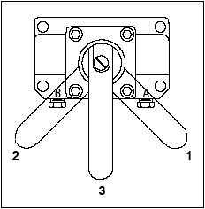
Position 1 (handle to the right, away from the
blue press) is for retracting the ram -
it connects the retract reservoir of the press to the high pressure outlet port
of the immersion pump and allows the advance reservoir to dump back into the
pump's ambient-pressure tank.
Position 2 (handle to the left, towards the blue press) is for advancing the ram and holding high pressure during runs - it connects the advance reservoir of the press to the high pressure outlet port of the immersion pump and allows the retract reservoir to dump back into the pump's ambient-pressure tank.
This is the opposite of what it says in the Enerpac manual.
We never use position 3 (handle in the middle)
for anything. The pump should be in Position 2 at all times during a run and in
Position 1 at all times between lowering one run onto the rails and being ready
to raise the next run off the rails.
When pumping the Enerpac immersion pump either direction, the four-handled valve in the hose system near the top of the yellow cylinder must be open. Once you are done using the Enerpac pump, close this valve. The limit for using the enerpac pump is 100 Tons, but we normally switch over from fast pumping on the Enerpac to slow pumping with the high-pressure system between 15 and 35 Tons.
The High-pressure cylinder and pumping system
In order to work at high loads (above 100 Tons) and to achieve smooth, slow compression and decompression, we use the high-pressure pumping system that sits on the massive blue table to the right as you face the press. This consists of a hydraulic cylinder, a worm gear that drives the piston into and out of the cylinder, a reducing transmission, and an electric motor controlled by the pressure control box on the west wall of the lab. There are overtravel limit switches at the top and bottom of the piston travel; we normally end each run by pumping all the way down until the bottom limit switch is engaged, and start each run by advancing the motor just far enough to disengage the limit switch. How to do this is explained in the checklist.
The pressure control box, as customized
There is a Rockland-supplied manual for this system here, but anything in this document supercedes that stuff because we have made extensive modifications.
First, let's name the controls, so we can talk about which ones to use, when:
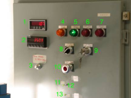
1. Motor Speed indicator: reads in RPM. Positive rotations means the pump is advancing (compressing); negative means the pump is retracting (lowering pressure). Practical limit for routine use is ±1650 RPM. Under LabView interface later, we will drive the motor in units of volts; the conversion from control voltage to motor speed is ~200 RPM/Volt, so the maximum control voltage for routine use is ±8.5 V.
2. DP41 Pressure display and controller. This device shows the pressure measured by a digital transducer connected to the hoses near the top of the yellow high-pressure pump cylinder. It display in units of US Tons, using a nominal conversion from pressure in the advance reservoir to force on the ram. This device also stores two pressure setpoints, compares the pressure reading to the setpoints, and affects the further logic of the pumping system based on this comparison. In Panel mode, if other settings are appropriate, the pump will advance to raise pressure so long as the pressure reading is below SP1, and the pump will back off at a very slow rate (-10 RPM) if the pressure rises above SP2. SP2 must always be greater than SP1 or the unit may become confused. We do not use SP3 or SP4. In LabView mode, the DP41 acts as part of a backup/safety system, such that LabView is only allowed to operate the motor if the pressure reading is lower than SP1.
3. Motor Speed Potentiometer. This is a ten-turn variable resistor that serves two functions: in Panel mode, it sets the speed (in unsigned RPM, 0 to 2000) at which the motor will run forward when (a) the INC/DEC switch is on INC, the limit switches are not engaged, and pressure is below setpoint, or when the bypass key is turned to Forward, and (b) the speed at which the motor will run backwards when the INC/DEC switch is on DEC. In LabView mode, the potentiometer must be set so that it corresponds to a speed of at least 1000 RPM, but it does not control the speed; it is only part of the backup safety circuit. Therefore, Rule: When using LabView mode, first go to Panel mode and set the potentiometer to >1000 RPM, then switch to LabView mode.
4. Decrease Pressure Light. Illuminates when pressure is above SP2 on the DP41; in Panel mode, corresponds to pumping down at very low speed -10 RPM. In LabView mode, this light is meaningless.
5. Increase Pressure Light. Illuminates in Panel mode when all conditions to run pump forward are met: pressure less than DP41 SP1, INC/DEC switch on INC, and no travel or pressure fault. Corresponds to motor running forwards at speed set by potentiometer. In LabView mode, this light should be on all the time unless something is wrong.
6. Over Travel Fault Light. This illuminates when the worm-gear driven piston hits either end of its travel range. If you hit the top of the travel, and have not achieved your pressure yet (or the system is leaking) this is trouble (see two-stage pumping). We usually end every run by running down until you hit the bottom travel-limit switch and this light illuminates. You will need to pull and hold the Stop/Start switch and turn the bypass key to FOR for about 1 minute (at 1650 RPM) to cancel this fault.
7. Pressure Fault Light. This illuminates when the system senses a sudden drop in pressure, which stops the motor. This will happen on blowouts, but there are also false alarms now and then. To cancel this fault condition, turn the system off and on again with the stop/start switch.
8. INC/DEC switch. In Panel mode, this puts the system in one of three states: INC means the system will pump forward at the speed given by the Motor Speed Potentiometer if the pressure reading is lower than SP1 on the DP41 and there are no overtravel or pressure faults; in INC mode the system will also pump backwards at -10 RPM if the pressure reading is higher than SP2 on the DP41 and there are no faults. DEC means the system will run backwards at the speed given by the potentiometer no matter what the pressure reading is, until you stop it or it hits the bottom travel limit switch. In the neutral position between INC and DEC the motor will not move no matter what. Furthermore, this switch must be on INC in order to enable LabView mode. If this switch in not on INC, you are in Panel mode, no matter what the LabView/Panel switch says.
9. Bypass key. This will run the motor forwards or backwards at the speed given by the Motor Speed Potentiometer no matter what the pressure and setpoints are and even with faults lights illuminated. It is used to move the worm-gear driven piston off the travel limit switches. Note that you need to hold the stop/start switch out until you turn the key; then as long as you hold the key turned you can let go of the stop/start switch.
10. Stop/Start switch. Pull to start (i.e., turn on the power to the system), Push to stop (shut off the whole pressure system). If the overtravel fault is lit, the system will not stay on unless you hold the start switch pulled, at least until you turn the bypass key.
11. LabView mode light. This green LED will light when the LabView/Panel switch is in LabView position.
12. LabView/Panel switch. Put this switch in the up position for Panel mode, which means the Pressure control box works as specified in the Rockland manual. Put this switch in the down position to attempt to go into LabView mode, wherein the PC may be able to drive the motor. Note, however, that the Panel controls still act as backup safeties: the panel must be generating a pump-forward signal corresponding to at least +1000 RPM in order for LabView to be able to do anything; see LabView enable light, control 13.
13. LabView enable light. This shows whether all the backup conditions are met to allow LabView to actually drive the system. That means (1) the power must be on, (2) no pressure or overtravel faults, (3) INC/DEC switch on INC, (4) Motor Speed Potentiometer at >1000 RPM, (5) Pressure reading must be lower than SP1 on the DP41, and (6) LabView/Panel switch in LabView position. The Boolean and of these five conditions is shown by whether this light is illuminated. If it is not lit, then the system is in Panel mode, regardless of the position of switch 12.
DP41 Panel Meter and Pressure Controller
This device displays the reading from the digital pressure transducer, stores two setpoints, outputs a logic signal depending on whether the pressure reading is greater than or less than these setpoints, and also provides RS232 serial input/output communication with the PC (so that LabView can read the pressure and, in the old VI, change the setpoints).

You need to know how to change the setpoints on the DP41 manually. At present, LabView does not do this for you. Rule: you must set the setpoints on the DP41 at the beginning of every run, whether it is a Panel run or a LabView run. Here is the procedure:
1. Make sure the LabView VI is stopped or paused. If LabView tries to communicate with the DP41 by serial line, it issues a RESET1 that kicks you out of setpoint programming mode.
2. Press the SETPTS button once to see SP1. In Panel mode, the system will pump forward if the pressure reading is below SP1, so for a Panel mode run you will want to set this exactly to your desired load. In LabView mode, the pressure must be below SP1 for anything to happen, so set SP1 to your desired load plus some error margin (perhaps 2 tons); that way most normal control will be handled by LabView but if LabView freaks out the system will not run very far past your desired pressure.
3. Press the Right arrow button to move the flashing cursor across to the digit you want to change.
4. Press the Up arrow button to cycle through the digits 0-9 until you get the one you want in the position where the cursor is flashing.
5. When all the digits of SP1 are right, press SETPTS again to access SP2. In Panel mode, when the pressure is above SP2 a very slow and almost useless pumpdown rate of -10 RPM is engaged. In LabView mode SP2 does not do anything. However, Rule: SP2 must always be greater than SP1 or the results are unpredictable! Recommended value is 0.2 - 1.0 tons higher than SP1.
6. Dial-up the desired SP2 using the Right and Up arrows as before.
7. Press SETPTS three times to get back to RUN mode. SP3 and SP4 do not do anything.
You should need to use the MENU or RESET buttons at all.
Two-stage pumping
Warning: this procedure has never actually been used or tested, proceed with caution. In principle, if compressing to very high load (perhaps >850 tons), especially if high-pressure pumping was started at low pressure (say, <20 tons), it is possible that the worm-gear driven piston may hit the top limit switch before desired run pressure is achieved. In this instance, we have a system that may allow you to achieve the needed extra stroke. Here is the procedure:
1. Note the pressure reading on the DP41 carefully; you will need to return the system to exactly this pressure later on.
2. Close the two-stage pumping valve (item 8 in the schematic above) to seal off the advance reservoir of the press.
3. Put the INC/DEC switch on the press control box on DEC. If you have actually hit the top limit switches and the system is showing over-travel fault, then pull and hold the Stop/Start switch and turn the bypass key to Reverse long enough to cancel the overtravel fault so that the system continues to run backwards when you release the key.
4. When pressure on the DP41 readout drops below 20 Tons, open the four-handled valve (item 7 on the schematic above) to connect the enerpac immersion pump to the system. The handle on the enerpac should still be in the advance position, towards the press (position 2 in the sketch).
5. Continue to back off the worm-gear driven piston until you have gained enough extra stroke to finish your run. Use about half the total stroke of the piston.
6. Use the enerpac immersion pump to refill the high-pressure pumping cylinder to 35 Tons pressure reading. Watch the oil level carefully - this operation uses more oil than anything else we do. If you have to add oil for this step, then remember to watch for overflow at the end when it all comes back out.
7. Close the four-handled valve to isolate and protect the enerpac.
8. Run the motor forwards until you recover exactly the pressure reading noted in step 1. Hopefully if you've taken on extra oil this will happen long before you hit the top of the stroke again.
9. When pressures are equalized, open the two-stage pumping valve. Ideally the system has held pressure and this will not shock your run at all.
10. Continue to your run pressure as if none of this had happened.
11. Nothing special should be required during the decompression stage.
The cubic module
The octahedral module
Castable
Gasketed
The heating system
The heating system generates an AC voltage difference between the top platen of the module and the reset of the press and so delivers current through the driver blocks and anvils to the heating element inside the run. Here is a schematic of the heating system:
- The heating control box includes the Eurotherm controller and SCR which are the heart of the temperature control system.
- The PC and LabView system are passive recording devices only, from the perspective of the heating and temperature system. They do not control, they only record.
- The Buck-boost transformer steps up the supply voltage from 208 to 240 V.
- The Tap-Changing Box allows switching of the secondary cables of the transformer between series and parallel configurations. For 48 V (5:1) mode, it must be in series position. For 12 V (20:1) mode, it must be in parallel position. For 24 V mode (10:1), it can be in either position, but only if it is in parallel position will the switch on the heating control box read 24 V when you are in 24 V mode.
- The Main Transformer has four taps on both the high and low voltage sides. Switching the high voltage side between parallel and series is done by the 12/24V switch on the heating control box. Switching the low voltage side is done by the tap-changing box. In these various configurations, the transformer accomplishes either a 5:1, 10:1, or 20:1 step-down in voltage and a corresponding step-up in current.
- Thermocouple is a disposable element inside your experiment.
- Screw terminal panel is where the compensating thermocouple leads from each module are joined to the compensating wire leading to the controller. Here you must switch between cubic and octahedral module leads so that your experiment is actually connected to the controller. Critical: do not reverse the leads when switching between modules; one wire is marked in red, and it goes to the red screw, which goes the red lead, which goes to the blue side of the thermocouple.
- Ammeter clamp measures the current through one of the secondary transformer cables on its way to the press. There is a switch on this clamp unit: it should be set to 400A mode for 12V runs (graphite heaters) and to 40A mode for 48V runs (LaCrO3 heaters), and should be turned to the middle (off) position when not in use. If the red light does not go on, the battery is dead and the current reading will be unreliable.
- Digital Multimeter reads the AC voltage generated by the Ammeter clamp (1 amp = 1 mV), and sends digital output to LabView. To enable digital output, you must hold down the Rel% button while you turn the multimeter on to ACV mode. This also disables the auto-shutoff feature, so the battery will run down quickly. Turn the multimeter off when not in use.
The Heating Control Box
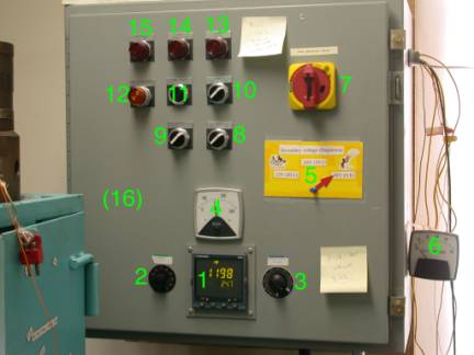
Let's go over the parts of the Heating Control Box, numbered in the figure:
- Eurotherm 2404 Controller. The manual for this device is here. This is your primary heating control device; it displays the thermocouple reading and the percent heating power; it has manual and automatic modes, and flexible temperature ramp programming.
- Current
limiter. This knob
enforces a hardware limit on the output of the system, to protect the
fuses and in some cases to prevent the system from misbehaving. It should
generally be left in the 9:00 position, unless your run needs more than
~20 primary Amps.
- Control
signal damper. This knob
modulates the control signal that goes from the Eurotherm 2404
Controller to the Eurotherm
470 SCR. It can be
used to quickly reduce power in an emergency without actually shutting off
the system. Usually, it has only one important function, preventing a big
power spike when you turn the Heat switch on. See steps A2 and DX in the checklists.
- Voltmeter. This shows the primary AC voltage being delivered
to the transformer. This value is modulated between 0 and 240 V by the
SCR. If you see 240 it probably means you have no heating circuit, see
troubleshooting. If you see 0 it means either the system has not started
up or you have a short-circuit, see troubleshooting.
- Voltage
Indicating Arrow. This
high-tech device shows what step-down configuration the system is in and
should always be set to match the positions of the 12/24V switch
and Tap-Changing
Box.
- Ammeter. This shows the primary current being delivered
to the transformer. It should never exceed 35 Amps, the rating of the
system fuses.
- Shutoff
switch and box latch. This is the
latch for opening the temperature control box, and also acts as a shutoff
switch. If you need to operate with the box open, you have to defeat this
safety by turning the square rod connecting this switch to the backplane
90° with a wrench. Turning this switch off will trigger the power
failure light and needs to
be reset with the start/ reset button (11).
- Heat
switch. This switch
controls the ability of the system to send any power to the transformer.
In the OFF position, the controller is on so you can check thermocouple,
set up controller, etc., but you cannot heat your run. In the ON position,
the system can deliver power. Therefore: Rule: the Heat switch should
always be OFF except during the actual heating step of an experiment.
Furthermore, there is the possibility of a big power spike as the
system charges up the transformer when you turn the Heat switch on.
Therefore: Rule:
always turn the Control Signal Damper all the way counter-clockwise before turning
the Heat switch to ON, then turn the Control Signal
Damper all the
way clockwise again. Note: Heat switch off does not provide
sufficient safety to go in and mess around with the Tap-Changer Box; this
requires the Power switch
to be off also.
- 12/24V
switch. This flips
the primary (high-voltage, low-current) side of the transformer between
parallel and series configurations. See Tap-Changing Box for a
through description of voltage step-down selection. In short, however, for
12V (graphite heater) operation use 12V setting, and for 48V (LaCrO3
heater) operation use 24V setting. Important consideration: The primary
voltage configuration will not switch except when the Heating Control Box
is being switched on, so you must turn the Power switch off and back on every time you want to
change the position of the 12/24V switch.
- Power
switch. This shuts
off all power to the Controller and SCR. You must cycle this switch to
change the voltage configuration. You must shut it off to open the Tap-Changing
Box. Otherwise
usually leave it on and rely on the Heat switch to prevent accidental heating.
- Start/reset
button. If the Power
Failure light (13) is on,
push this button.
- Dev.
Alarm reset light. Does not do
anything.
- Power
Failure Light. This will
illuminate after a true power failure, a blown fuse or flipped circuit
breaker, or after the Shuttoff switch and box latch switch has been turned off. Press the Start/reset
button (11) to make
it go away.
- Over-temperature
light. This does
not do anything.
- Pressure
Failure Light. This does not
do anything.
- Eurotherm
470 SCR (inside the
box). This is the device that actually takes the desired output level requested
by the controller and cyclically makes or interrupts the circuit so as to
achieve the desired RMS power. The manual is here. The
behavior of this SCR is a little complicated: it monitors both voltage and
current and attempts to deliver a power = VxI that is the desired fraction
of nominal maximum power. We are only using a small fraction of this
instrument's range; the scaling of 0 to 100% on the controller to the
actual range of SCR power we are using is set by the C1L and C1H
parameters on the controller. See controller
configuration.
Controller configuration
Into this category fall several procedures that you should not need to do routinely; for the most part one configuration works for everything. However, for the record some steps that may be necessary from time to time are here.
1. Output scaling. The SCR is not configurable: it takes a control signal between 4 and 20 mA and linearly scales this to a desired power between 0 and 18000 W. We never need 18 kW, and we want to have the most control sensitivity within the limited range we actually need, so we rescale the controller such that 0 to 100% in the OP display corresponds to a much smaller range of control currents to the SCR. We have an optimum range that seems to work for all cubic and octahedral configurations at present, but we do have to change it now and then (for instance when we swap SCR units). It works like this:
Usually, UAL.L = 0, UAL.H = 100. Also, usually, Out.L ~ 4.3 mA and Out.H ~ 7 mA. Between 0% OP and 0.1% OP, the control current will jump from <4 mA (which keeps the SCR from doing anything) to Out.L.
2. Setting Thermocouple type. This is pretty intuitive now. On the IP configuration menu, the first parameter, inPt, should be set to C.tc for W/Re 5/26 and to k.tc for type K thermocouples, etc.
3. Tuning. This can be a big mess. See the Controller manual for a discussion of PID tuning. Hopefully we will continue to get good results with the present parameters, otherwise maybe I will write a discussion of recommended tuning techniques for our application here.
The Tap-Changing Box
With our transformer, we have the capability to run the heating system with three different ‘stepdown’ ratios between the primary voltage (0-240V) and the secondary voltage that goes across the platens of the multianvil module. The possible stepdown ratios are 20:1, 10:1, and 5:1, which correspond to fullscale secondary voltages of 12V, 24V, and 48V, respectively. We achieve these configurations by switching the leads going into the four primary taps and the four secondary taps of the transformer between series and parallel configurations. This is somewhat confusing, in particular because there are four physical configurations, two of which are degenerate from a working point of view because they both give 10:1 (24V) output. Schematically, here is how it works, with all voltages being fullscale voltage (i.e. with the SCR running at 100%):

I recommend using configuration 1 (12/24V switch on temperature control box at 12V; tap Changer in so-called “24V” mode) for 12 V (20:1 stepdown) operation; configuration 3 (12/24V switch on temperature control box at 24V; Tap Changer in so-called “24V” mode) for 24 V (10:1 stepdown) basically for the sake of clarity; and configuration 4 (12/24V switch on temperature control box at 24V; Tap Changer in so-called “48V” mode) for 48 V (5:1 stepdown).
To change the taps on the Tap Changer:
- Shut
off the power using Power switch (10) on the Temperature
Control Box.
- Open
the Tap Changer box.
- Use a
wrench to remove the nuts holding the bus bars on.
- Consult
the following pictures to see how to put the bus bars back on:


- Put nuts on the appropriate bolts and tighten them securely to hold the bus bars in place. If you were in 48 V mode, the extra nuts should be on top of the Tap Changer Box.
- If you did not use all the nuts (in 48V mode), place the extras on top of the Tap Changer Box.
- Close the Tap Changer Box.
- Set the 12/24V switch on the Temperature Control Box as desired.
- Put the Voltage Indicating Arrow on the appropriate setting that you just chose.
- Turn the Power Switch back on.
The LabView interface
Checklists
Section A: All Multianvil experiments